Accelerator Components
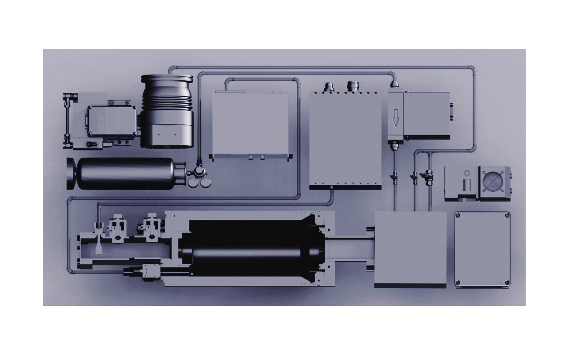
The Alpha-E particle accelerators are flexible tools with an extensible modular target assembly. The system has been designed to provide optimal reference measurements of fusion products with minimal exposure of the user to ionizing radiation.
Alpha Ring's provides the following components on a standalone basis
- Ion Beam Source
- High-Voltage Power Supply (HVPS)
- Vacuum Pumps
- Pressure Control System
- Particle Detectors
- Modular Target Assembly
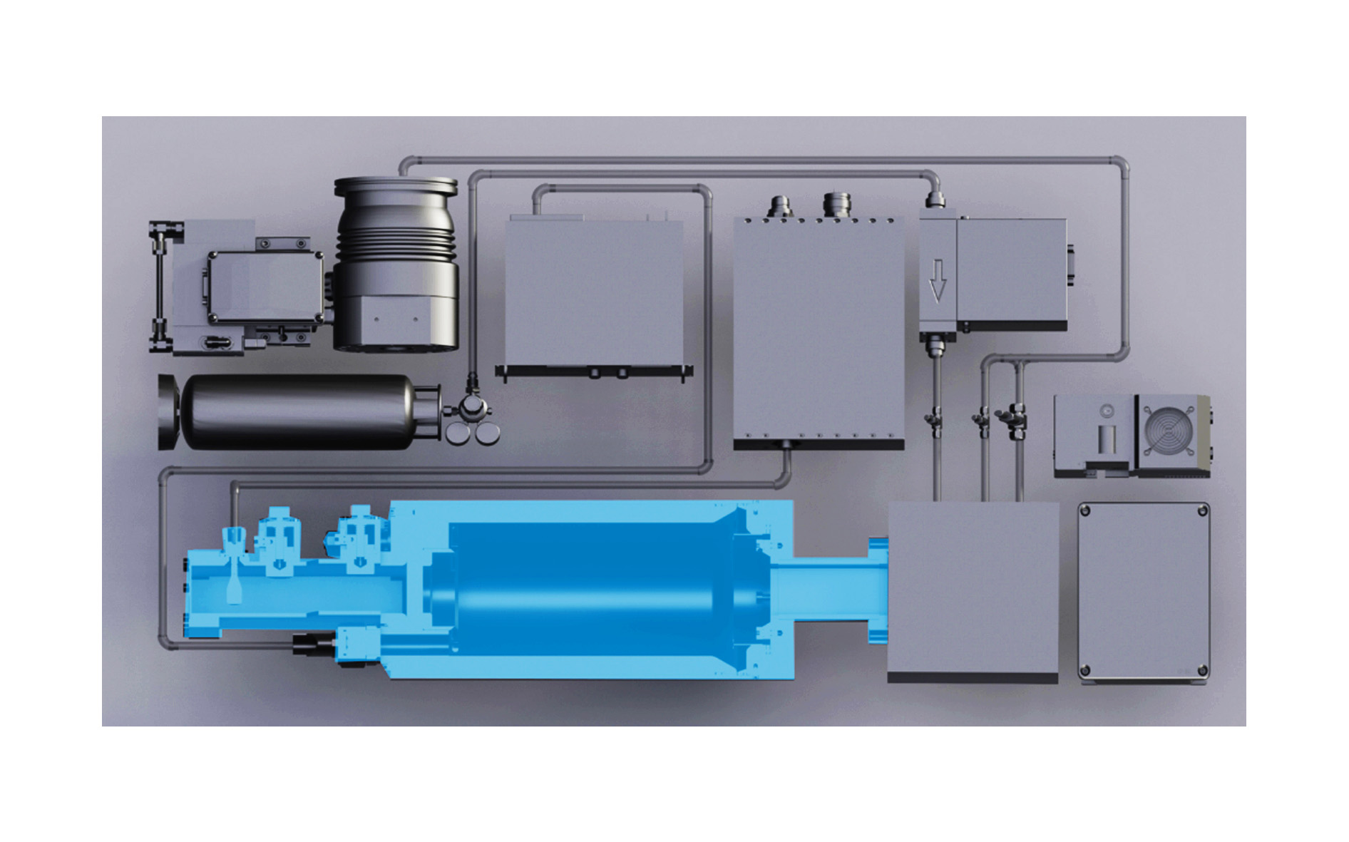
Ion Beam Source
The ion source is the heart of the Alpha-E accelerator system.
The main housing of the ion source encloses the plasma-forming cavity and ion optics used to form the ion beam. On one end is the microwave coupling assembly for electron cyclotron resonance (ECR) excitation and input ports for the acceleration voltage and the cooling fluid. On the other end the beam output flange connects to the modular target assembly.
Modular Target Assembly
The user can define variable test conditions through simple modifications of the target chamber.
The assembly that typically houses the fusion target is constructed with standard CF type flanges, matching the output port of the ion source. The user can, therefore, set up many different configurations of targets, detectors, and electrodes.
In the simplest configuration, a solid target is mounted in the path of the ion beam. The composition of the target depends on the experimental needs. If the experiment requires a beam, but not necessarily nuclear fusion, the target can be replaced with Faraday cup or other sensor to measure the beam characteristics. The user could also install ion optics to extend or manipulate the beam.
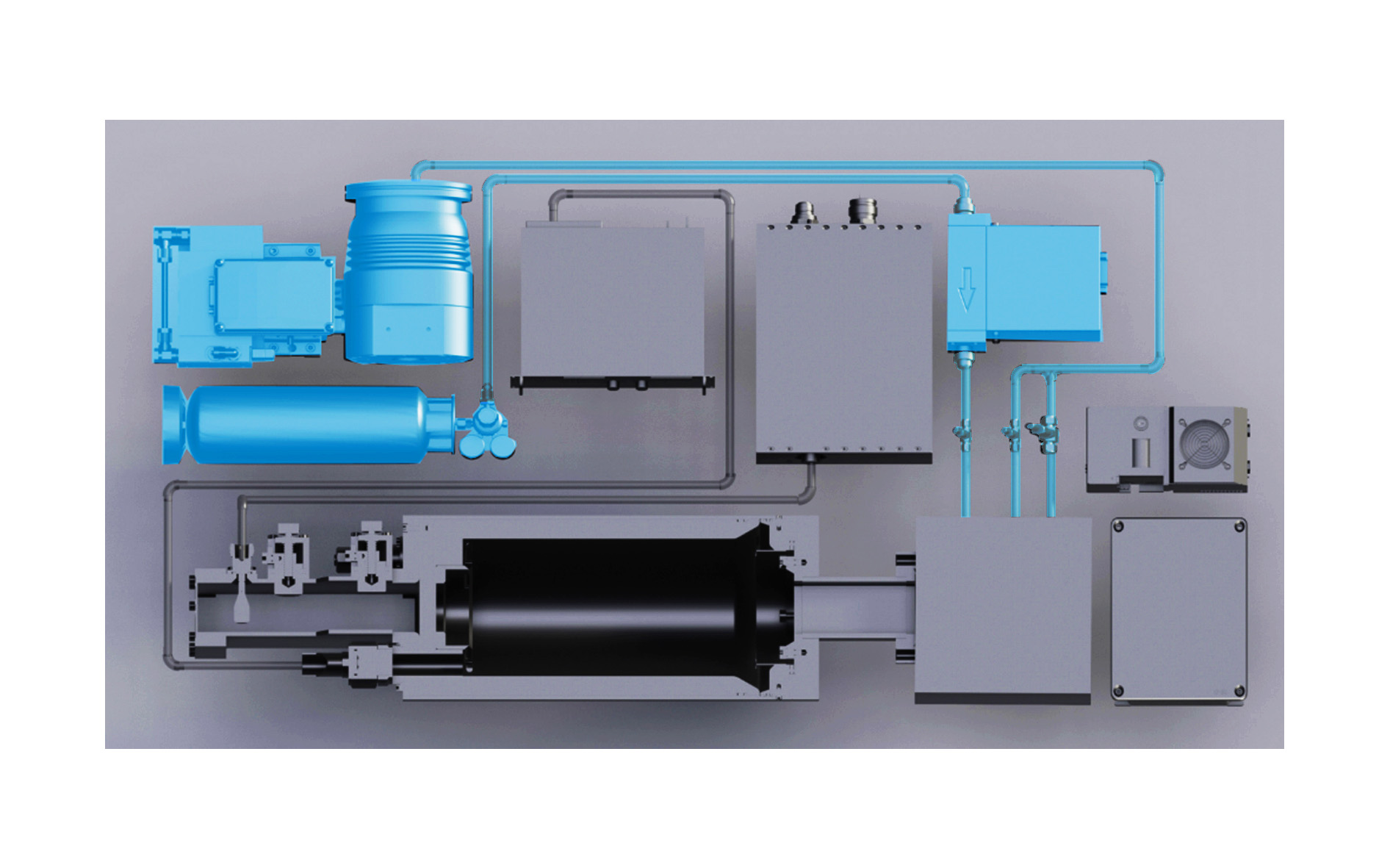
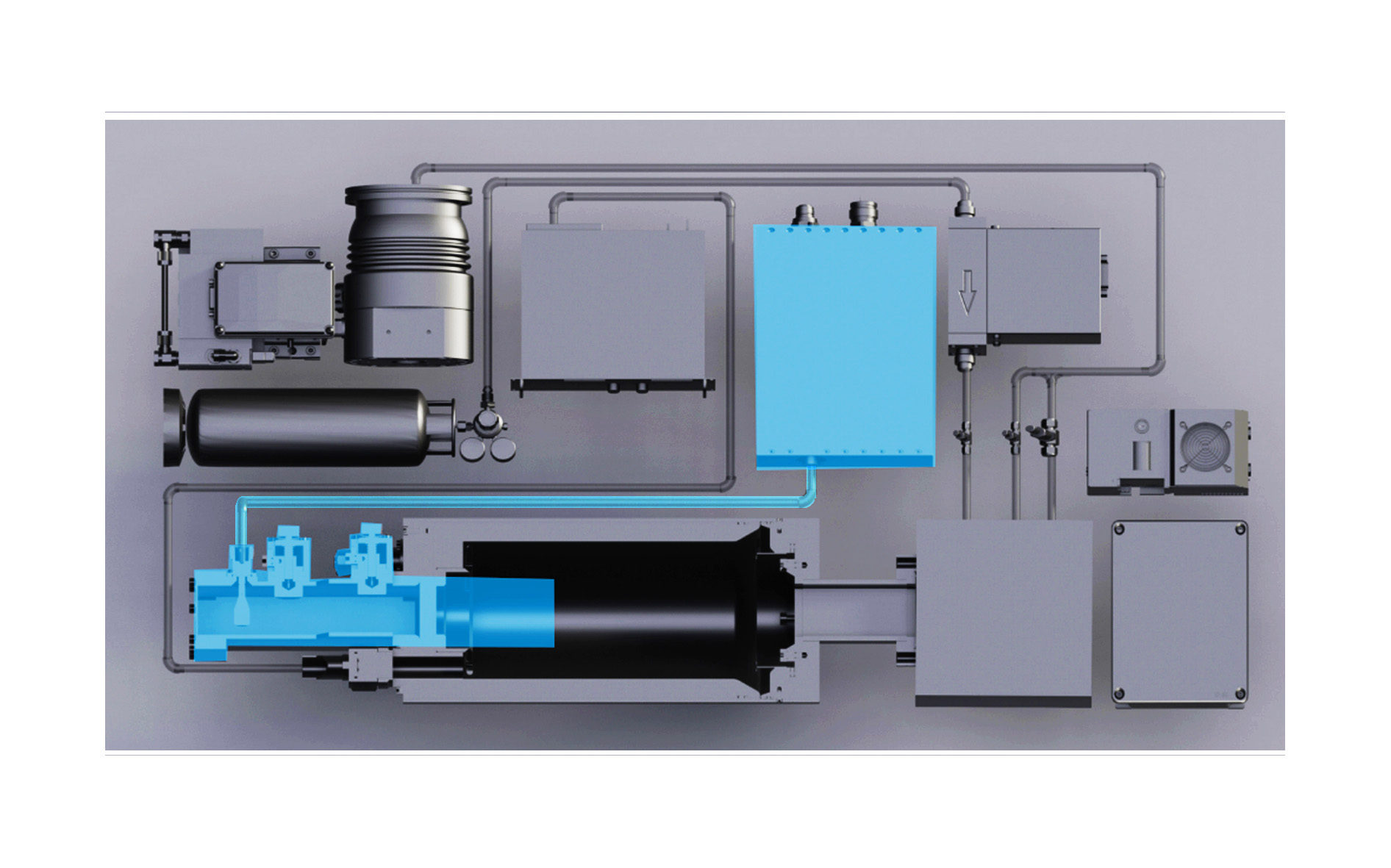
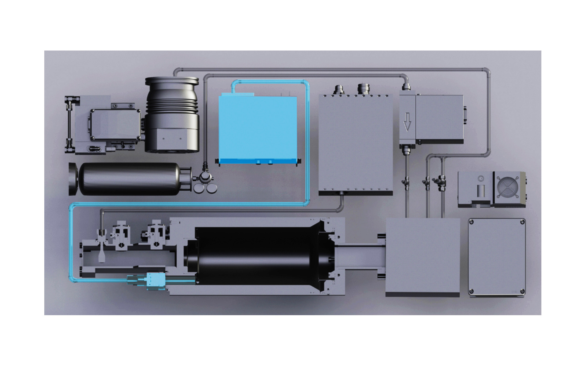
Vacuum Pumps and Pressure Control
The Alpha-E system is designed to operate with hydrogen or deuterium as the neutral gas for plasma ionization.
Gas flow is regulated using a mass flow controller (MFC). A turbomolecular pump system is needed for operation of the ion beam. In typical operation, the input gas flow is balanced against the continual vacuum pump operation to establish and maintain the pressure needed to form the plasma in the ion beam source.
Microwave Source
Microwave power ionizes the supplied gas by electron cyclotron resonance (ECR).
The unit includes a solid-state oscillator and a series of amplifiers and signal conditioning hardware. The amplifier gain is kept fixed, and the user can vary the output power by adjusting an attenuator using the provided software. For typical operation, the 2.45-GHz microwave source is pulsed at a rate of 100-1000 Hz at a 5-10% duty cycle.
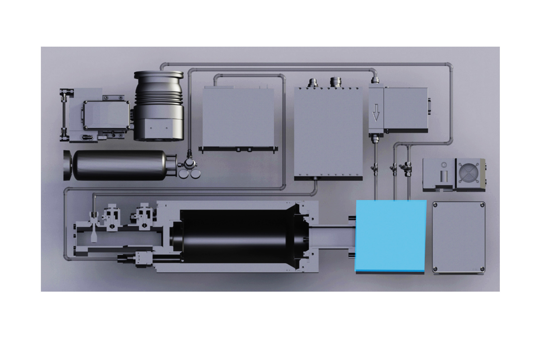
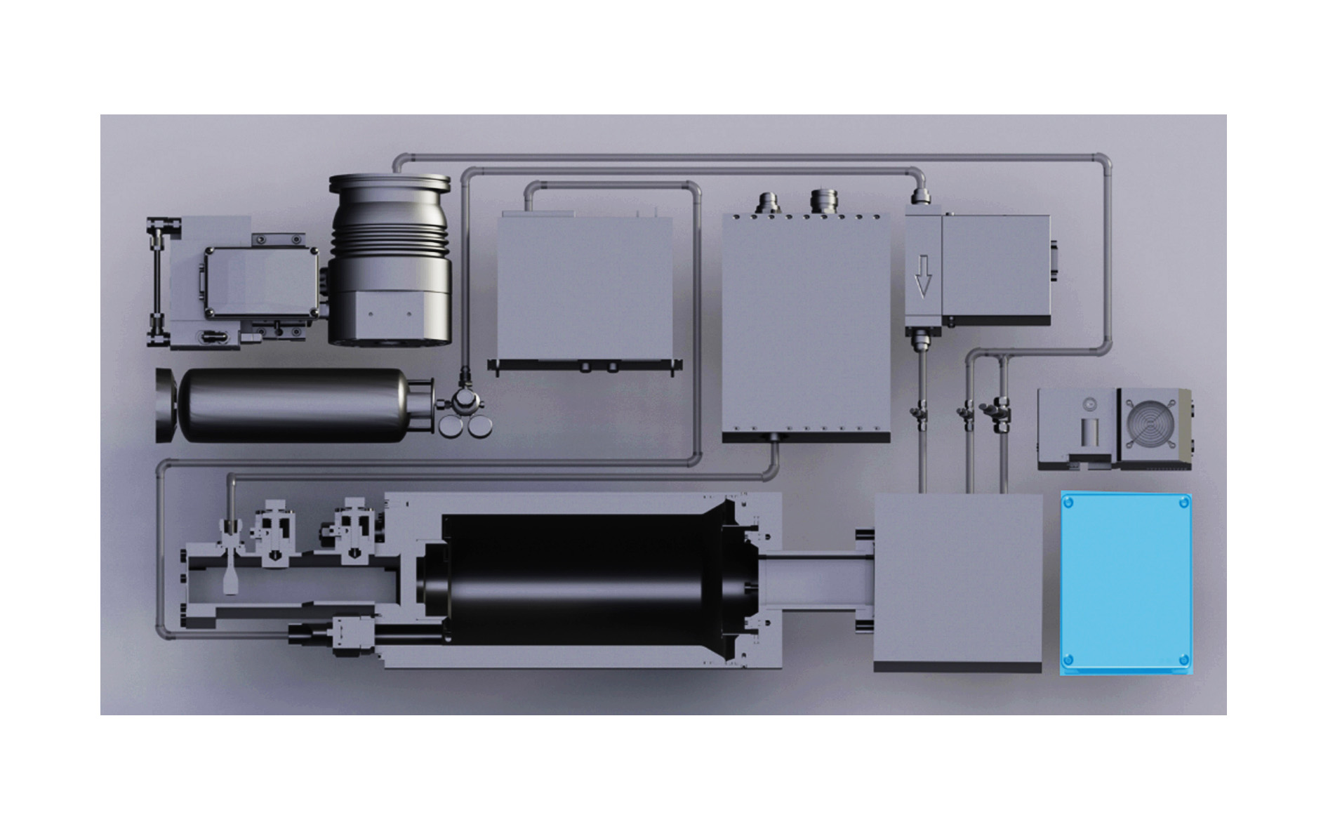
High-Voltage Power Supply
The acceleration voltage is provided by a high-voltage power supply (HVPS).
The HVPS units included in the Alpha-E accelerator generate up to 30 kV using flyback transformers. Higher acceleration potentials require an external power supply and additional shielding.
Detection Systems
A suite of detectors and measurement systems yield data related to those in more complex plasma and fusion systems.
The standard configuration of the Alpha-E accelerator includes two particle detectors and sensors for measurement of gas pressure, temperatures, and other operating conditions. Additionally, the modular system can accommodate a large number of both commercially available and custom designed detection systems.
RF Source
Drive ECR plasma generation with a configurable 2.45 GHz microwave source.
The RF/MW source supplies the excitation power for the electron cyclotron resonance (ECR) plasma in the ion source.
- Frequency: 2.45 GHz
- Peak output power: 500 W
- Output impedance: 50 Ω (Type-N connector)
High-Voltage Power Supply
The Alpha-E HVPS uses a flyback transformer topology with an 8-stage Cockcroft-Walton multiplier.
Key specifications of the Alpha-E internal HVPS include flyback driver topology with UART over fiber optics communication.
- Maximum operating voltage: 30 kV or 75 kV
- Maximum operating current: ~150 µA
- Input voltage: 12–36 VDC, 1 A max